Controls


∆ Image 8a: Command buttons

∆ Image 3d.25: Control Buttons Task
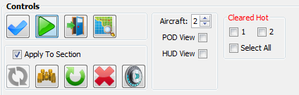

Validate

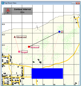
The check mission button is clicked to update and depict the task values into the ‘Top Down View’ window. The visual representation of the task can be viewed prior to committing to an attack.

Execute

This button is clicked to instruct the aerial asset to commence the attack

End Mission

Ends the selected Mission on Missions table
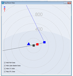
View Map

This displays OTL (Observer Target Line), FAH(Final Attack Heading), LTL(Laser Target Line) and Laser Basket values on Strike Top Down View. These values can be Enabled/ Disabled selecting or Deselecting the check boxes in Top Down view map.

∆ Image 8a: Command buttons

∆ Image 3d.26: Top Down View


If map objects are placed inside the folder %USERPROFILE%\Documents\VBS3\VBS3Strike, when View Map button is clicked, the panel graphically displays the task selected via the Tasks table. This contains layers which will expose the details of the map. The amount of layers or the map detail needed for the mission can be selected from Preferences → Other → Map Layers. The selection of the layers should be done before starting the mission.


∆ Image 8a: Command buttons

∆ Image 3d.27: Top Down View

Apply To Section

If Apply To Section is selected and a New Target is set through HUD/ POD views then the new target will be set to the entire section. If a particular Air platform completed attacking then new targets cannot be set until the entire task is aborted. Select this check box to Update, Adjust, Re-Attack and Abort and Teleport serial to all air assets belonging to the air platform.

Update

This allows to change any of the details in a mission such as changing weapons, target, egress etc. And update the task accordingly when a mission is under the status of ‘Not commenced Yet’.
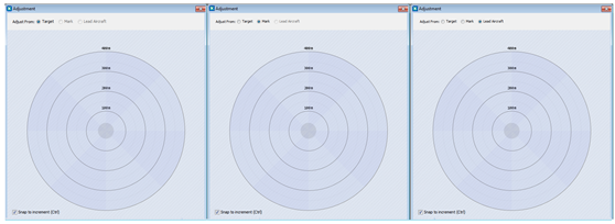
Adjust

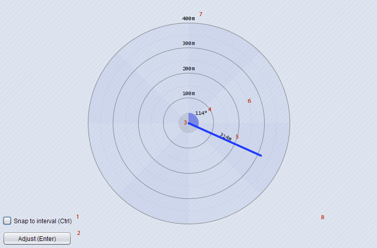
This button brings up the adjustment panel to give an adjustment (distance/angle) to where the rounds hit; by using the Resizable Multidirectional Range Picker approach.

Note :
This button will be activated for in progress tasks and completed tasks.

The adjustments can be given according to three locations.

  • Target - adjust the effective target location with respect to the original target grid we specified when the task was started. By specifying a value in meters, we can make the target shift along the corresponding direction.
  • Lead Aircraft - "Lead Aircraft" option would be available in “Adjust From” drop down menu only if leading aircraft has already attacked the target in a multi-aircraft task. By selecting “Lead Aircraft” option we can adjust the target with respect to the impact location of the Leading aircraft.
  • Mark - would be available only if you are using “Magic Mark” in the current task. By entering a value we can make the target shift with respect to the marked location ( by Smoke/WP or ILLUM) in corresponding direction.

∆ Image 8a: Command buttons

∆ Image 3d.28: Adjustment panel views (Target, Lead Aircraft, and Mark)


Features of the multidirectional range Picker:

∆ Image 8a: Command buttons

∆ Image 3d.29: Multidirectional Range Picker


  1. By pressing the CTRL key or by selecting this checkbox:
  • allows user to snap to ±45° interval's when mouse click and drag
  • allows user to snap to ±50m interval's when mouse wheel rotating (rotate forward to increment, backward to decrement) Snap to increment is selected by default.
  1. By pressing the ENTER key, by double clicking or by clicking the Adjust button, will submit the direction and angle selected by user
  • if user selects a distance less than 40m or does not select a value at all, action will do nothing
  1. Shows the minimum area of distance selection (40m)
  1. Shows the angle of user selection by a filled blue arc
  • if angle is an interval of 45° it will show the respective N, NE, E ... direction instead of the numeric angle
  1. Shows the user selected distance in meters
  1. The mouse sensitive region:
  • if the mouse is clicked, it will select a distance and an angle of the position that is clicked
  • if mouse is clicked while Snap to increment is enabled, it will select a distance and an angle which is closer to ±45° interval
  • if mouse is dragged, it will continually render the dynamic distance and angle
  • if mouse is dragged while Snap to interval is enabled, it will continually render the dynamic distance and angle which is closer to ±45° interval.
  • light and dark colored arcs represent boundaries to N, NE, E, SE, S, SW, W, NW directions.
  1. Range circles, representing distances from 100m to 400m (maximum value)
  • light colored range circles represent 50m intervals
  • dark colored range circles with text represent primary 100m intervals
  1. Outer area,
  • If mouse is being dragged (while drawing distance user goes to outer-area) the selected distance will be scaled to the maximum distance value (400m)

Re-Attack

This button is clicked to instruct the aerial asset to perform re-attack of an existing task entry. The aerial asset will mimic the mission data of that existing task entry.

Abort

This button is clicked to abort a strike task which has not yet started or is in the process. Tasks with status ‘Not Commenced Yet’ will be deleted when the task when is aborted. When a task is aborted, the task status will be changed to ‘Aborted’.

Air Platform

Select the Air Platform from which to switch to HUD view or POD view.

POD View

Select this check box to change the view of VBS3 environment to the POD view of the aircraft.

POD view automatically slews to the target location of the first task of each mission. If user doesn't interact with POD controls it will keep unchanged even though multiple tasks are created with different targets.

If user drags the camera while right mouse button is clicked or slew to any other location via the option provided in POD view, it will lock on to the newly moved or slewed location. If the user right clicks on POD view, the lock will be removed and the camera target will start moving with the aircraft motion.


If a new mission is created after ending the existing mission POD will slew to the first target of the first task of the newly created mission.

HUD View

Select this check box to change the view of VBS3 environment to the Heads-Up-Display of the aircraft.

Cleared Hot

If this box is checked, then the VBS3Strike assets will carry out the mission, else the assets will not fire at the target. The ‘Cleared Hot’ check box is disabled by default. It will be activated when mission is created. Firing when an aircraft is manually controlled requires ‘Cleared Hot’ check box to be selected.

Note:
If there are 3 planes available for a mission a “Cleared Hot All”, “Cleared Hot 1”, “Cleared Hot 2”, “Cleared Hot 3” check boxes will be available respectively in the Strike Instructor Control panel.

Situations where more than 3 aircrafts in a section, the user can select cleared hot checkboxes from the tasks panel in the Strike Instructor Control panel